
Introduction of MARK VI and MARK V gas turbine control systems refers to the advanced control of GE turbines, which have more than 30 years of brilliant history and successful performance. MARK VI gas turbine control system is designed as a complete and integrated control, protection and monitoring system for generator and mechanical drive applications of gas and steam turbines.
The gas turbine control system hardware and software are designed using General Electric Turbine Design Engineering and Control Engineering to ensure that the control system provides optimal turbine performance. With the Mark V and MARK VI gas turbine control systems, you will enjoy the unique experience of General Electric with an advanced turbine control platform.
Gas turbine control system is in the group of PLCs, which are designed only for turbine control, to have the best performance and trip on turbines. In general, this system alone is the most complete control device designed without the need for another system. Compatible architecture, high quality and high speed in exchange and strong processors in this system are due to Ethernet in the control layer, which is one of its advantages.
The General Electric Turbine Control (GE) control system is known as Speedtronic. This system is one of the most famous controllers, which is programmable and has a global reputation. The sales of this product in the market show its popularity as an old brand. This gas turbine control system with high installation request is one of the best gas turbine controllers in the world.

Familiarity with the structure of gas turbines
Before reading, you need to be somewhat familiar with the structure of the gas turbine, so that you can better understand the structure and control system of the gas turbine.
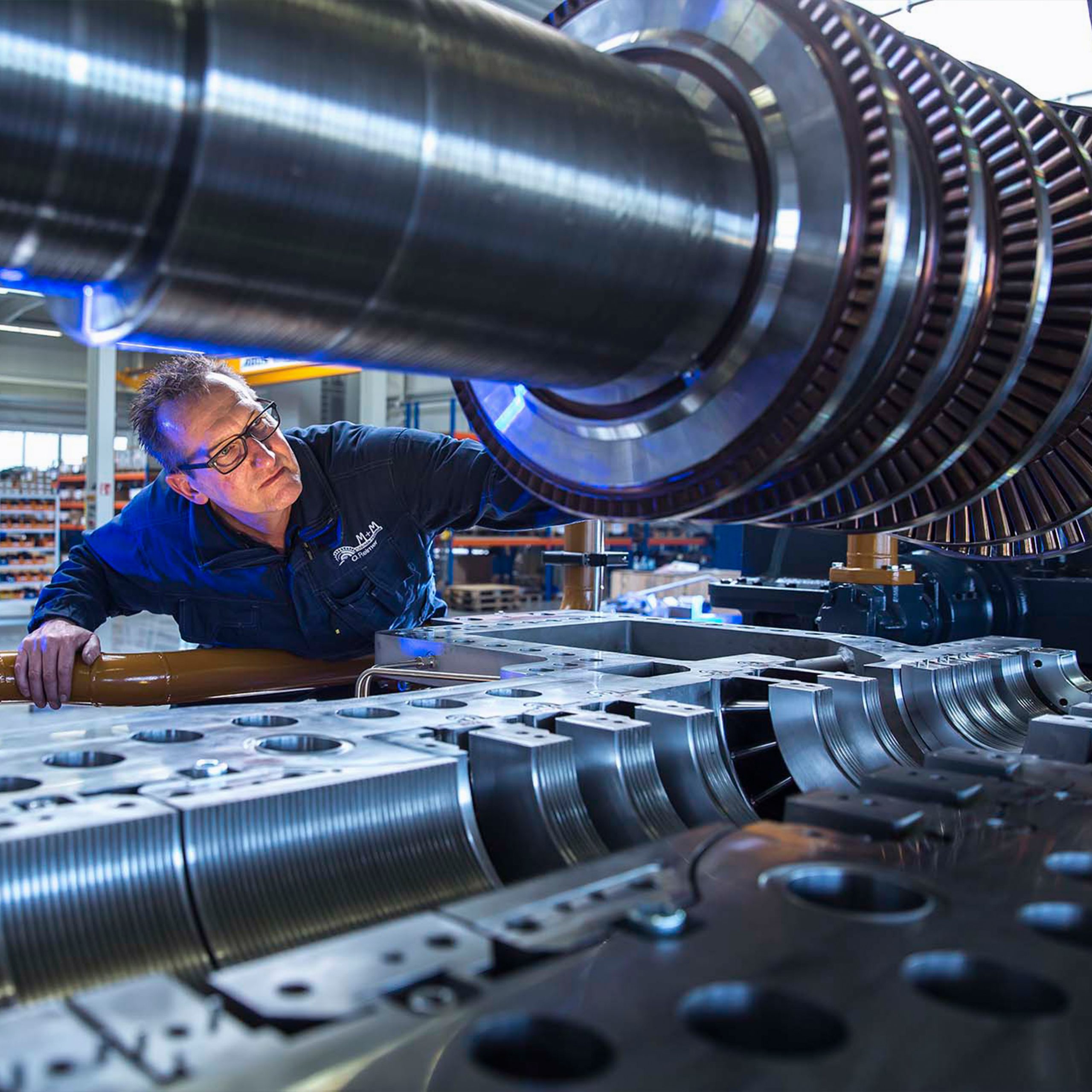
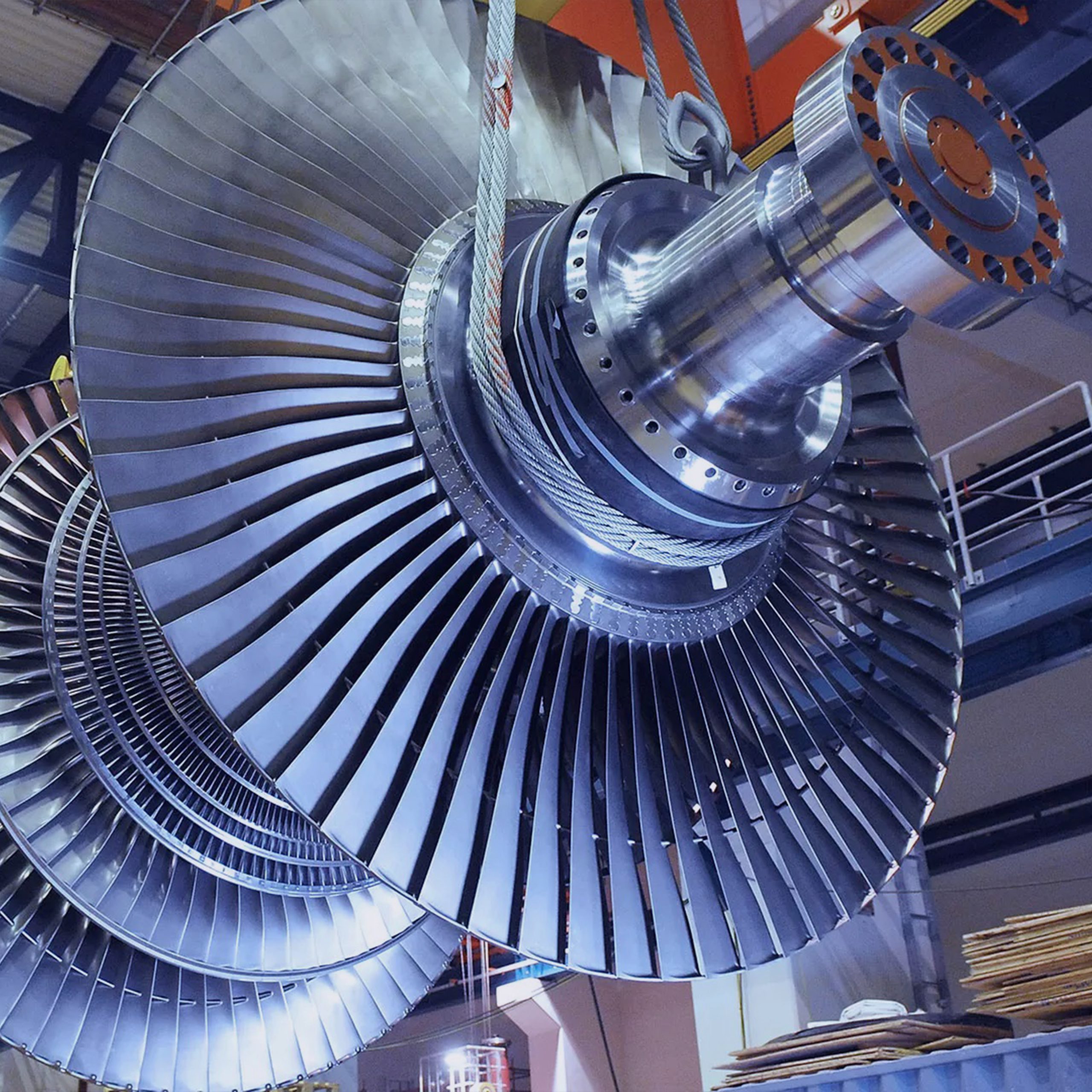
A gas turbine is a rotating machine that has an internal combustion engine and uses the energy of the gases generated by combustion. Turbines consist of several parts, including:
- Turbine, which converts the combustion energy of gases into mechanical energy
- Combustion chamber for mixing fuel with air and its combustion
- A compressor used to compress air
The mechanical energy produced in turbines is used for a variety of purposes, including the rotation of the turbine compressor, the rotation of the electric generator, the acceleration of air such as turbojets and turbofans, and so on. Gas turbines have 4 controllers, including:
- Load controller
- Speed controller
- Start controller
- Turbine load controller
The gas turbine control system can control the flow of fuel entering the combustion chamber, to achieve the following:
- Controlling the internal shell temperature of turbines and blades
- Shaft acceleration control as permitted
- Control the amount of loading to the extent that production units need
- Maintain constant shaft speed at loads

Design of gas turbine control system
Mark V and Mark VI gas turbine control systems use two simplex and TMR architectures, which have three controllers S, R and T. These systems have all the specifications needed to protect, control and monitor the turbine.
The gas turbine control system is the heart of the control module, which is contained in a standard VME card slot with 13 or 21 slots. The inputs and ventilation of the passive signal are received by the control module through the end panels with box-shaped pieces. Each I / O card contains a TMS320C32 DSP processor to digitally filter data before converting it to IEEE-854 32-bit floating point format.
The data is then stored in dual-port memory, which is accessible by the C32 DSP on one side and the VME bus on the other. In addition to input / output cards, the control module includes an internal communication card, a main processor card, and sometimes a flash drive.
Each card has one slot, except for the main processor, which has two slots. The cards are manufactured with surface-mounted technology and coating in accordance with IPC-CC 830.
The main processor card, depending on the needs of the program, runs most of the applications at a speed of 10, 20 or 40 ms. Since most programs require certain parts of the control to run faster (such as servo loops, pyrometers, etc.). The processor system distributed between the main processor and the dedicated input / output processors is critical to optimal system performance.
With the Mark VI gas turbine control system, you will enjoy the unique experience of General Electric with an advanced turbine control platform.
- More than 30 years of experience
- Complete control, protection and monitoring
- Can be used in various applications
- Designed by General Electric Turbine and Control Engineering
The data connection between the control module and other modules in the Mark VI gas turbine control system is done on IONet. The VCMI card in the control module is the main IONet bus, which communicates with subsequent stations on a 10Base2 Ethernet network. It should be noted that a unique polarity protocol (asynchronous drive language) is used to make IONet more secure than traditional Ethernet LANs.

The control module is used for control, protection and monitoring functions, but some applications need protection and support. For example, speeding protection and support are always required for turbines that do not have mechanical speed control.
IO modules are divided into two main categories:
- General Purpose I / O Multipurpose Modules
- Application Specific I / O software module
Multi-purpose I / O cards in gas turbine control system
Digital modules in gas turbine control system: VCRC card has 48 digital inputs and 24 digital outputs. Input / Output is divided between 2 end boards for connection inputs and 2 other boards for booster outputs.
Analog modules: The VAIC card has 20 analog inputs and 4 analog outputs. Input and output are divided between the two end panels. A VAOC is assigned to 16 analog outputs and interfaces with 1 end panel in the form of a barrier or 2 final panels in the form of a box.
Temperature control modules: Provides a VTCC card for 24 thermocouples and a VRTD card for 16 RTDs. Input cards are associated with 1 end board in the form of a barrier or 2 end boards in the form of a box. The monitoring capacity of 9 additional thermocouples is provided in the backup protection module.

IO control system software
In addition to the general input / output, the Mark VI gas turbine control system has a variety of cards that can be connected directly to sensors and actuators. This reduces or eliminates a significant amount of deleted electronic components and cards in many cases.
As a result, many single-point failures in sensitive areas are eliminated to improve performance and ensure performance as well as reduce long-term maintenance. It also has a direct interface with sensors and actuators that can troubleshoot and directly evaluate devices and equipment for maximum effectiveness. This data is used to analyze the performance of the device and the system.
The VTUR card is designed to integrate several unique sensor interfaces used in the gas turbine control system.

VALVE control card in gas turbine control system
In the gas turbine control system, the VALVE control task is performed by the SERVO control card. This card is a terminal with circuit board connection, whose function is to transmit VSVO card information. The control system is TRIPLE, which is suitable for the VALVE system and is designed for them.
What is a turbine protection card?
The most important part in the gas turbine control system is the part called the turbine protection control and it has a specialized card (VPRO). This card protects the entire system and prevents all slots from turning off. The turbine protection card is one of the most important parts of the gas turbine control system, which prevents severe damage during disruptions.
What is a vibration card?
One of the tasks of the gas turbine control system is to constantly monitor and control the turbine vibrations, check the data and related criteria. Also, providing the necessary commands and running this system is one of the most sensitive tasks. This is an important and sensitive task for the VVIB card, to be done professionally. This card processes the received information and sends it to the main processor via VME.
What is the function of a synchronous card in a turbine?
One of the most important control components in the gas turbine control system is the synchronous card. This important operation is possible using the VTURE card. All the desired tasks are planned according to the gas turbine control system. This card is connected to the CPU and provides how to receive and send all information under defined protocols and is able to provide reliability and accuracy in the operation of the control system.

Gas turbine control system repair cost
Due to the fact that General Electric parts are on the gas turbine control system components cards, its maintenance and repair costs are very low. These systems have performance with minimal depreciation and long service life, which reduces the need for repairs and lowers maintenance costs.
Having a GE dealership in many areas has reduced the need to consult miscellaneous equipment repairers, and with the presence of professional specialists on the job, costs have been reduced.
Application of modules
This gas turbine control system is one of the first modular systems in General Electric. In this system, troubleshooting or the need to replace the cards is easily done and in each row, all the cards are placed on a rack, which is connected to the central controller using the interface module.
The modules we mentioned are used in several cases, which can be referred to these options:
- Input speed
- Sync
- Combustion flame detection
- Sliding system
- Servo valve connection line
- Vibration and Proximitor inputs
- Optical pyrometer inputs
- Three-phase PT and CT monitoring
Input speed in gas turbine control system
Four-speed inputs from passive magnetic sensors are controlled by a VTUR card. Two-speed inputs are also monitored by a VSVO servo card and can communicate with passive or active speed sensors.
Sync system
This system includes auto-sync, manual sync, and backup sync check protection.

Combustion flame detection
The presence of a flame can be calculated from turbine parameters or from a direct interface to the Reuter Stokes or Honeywell flame detectors. These detectors detect the flame in the combustion chamber by detecting UV rays emitted from the flame.
Reuter Stokes detectors produce a 4-20 mm input. For Honeywell flame scanners, the Mark VI provides 335Vdc combustion and VTUR / TRPG detects the pulses of the current generated. This system determines whether the accumulation of carbon or other contaminants on the scanner window reduces light detection.
Sliding system
In turbines that do not have mechanical speed control screws, the slip control system can protect the module.
Servo valve connection line
In the use of TMR, usually 3 servos and coils are used to extend the amount of analog outputs to the servo coils.
Vibration and Proximitor inputs
The VVIB provides a direct connection to the Seismic Probe (Speed), Proximitor, Velomitor, and Accelerometer (via the Charger Amplifier). In addition, DC position inputs are provided for axial measurements and keyphasor inputs.
Three-phase PT and CT monitoring
The VGEN card acts as a dual interface for 3-phase PTs and 1-phase CTs. It is also a specialized control system for power imbalance and early activation of valves in large steam turbines.
Optical pyrometer inputs
The VPYR card with two LAND infrared pyrometers monitors the temperature characteristics of the turbine blades.
Operator interface
The operator interface is commonly known as the user interface (HMI). It is a PC with Microsoft and Windows NT operating systems, which supports server client capabilities. It has a CIMPLICITY graphical display system, a control system toolbox for maintenance, and a software interface for Mark VI and other network control systems.
Uses of the operator interface:
- The primary operator interface is used for one or more units
- A backup operator interface to the DCS operator interface
- Route for communication links to other control systems
- A permanent or temporary maintenance station
- Engineering workstation
All controls and protections are under the control of the Mark VI, which allows the HMI to be an unnecessary component of the gas turbine control system. In this case, it can be rebuilt or replaced with an ongoing process without affecting the control system. In graphic pages you will be able to see all the parameters and status of variables. Alarms in the turbine can also be stored
Maintenance of software in gas turbine control system
Mark VI is a fully programmable gas turbine control system. The software used is built using internal automation tools. In this system, they use GE control and protection algorithms to coordinate them with the inputs / outputs and displays of each program.
The time required for inputs, programming and execution of software and outputs is about 10, 20 and 40 seconds. To make changes and protect the software, you can define a password and use the modules during the process. All software used in the Control Module can be stored in flash memory.

Communications in the gas turbine control system
Communications are provided in the gas turbine control system to transmit internal data in a Mark VI control system. The UDH communication driver is located on the main processor card in the Mark VI. This is the card that runs the turbine application. Therefore, there is no potential connection point between the main turbine processor and other UDH control or monitoring systems.
In TMR systems, there are three separate processor cards that run the same applications from the same database. Two of the UDH drivers are usually connected to one switch, and the other UDH driver is connected to the other switch with a star configuration.
All operator commands can be issued to Mark VI (s) via a remote computer via HMI (s). The remote computer can also monitor any application data contained in the Mark VI. The system can monitor about 500 points at a time. However, with programming in the system, usually about 1200 points are accessible through communication links for support.
Various communication protocols can be used to communicate with other systems and DCS in the Speedtronic Mark VI control system:
- MODBUS TCP / IP
- MODBUS RS232 / 485
- Ethernet TCP-IP
Troubleshooting in gas turbine control system
In the gas turbine control system, each card in the control module can troubleshoot parts, including:
- Hardware applications
- Software system programs
- Timely detection of abnormal hardware conditions
Also, the low and high values in the inputs are automatically checked on each card. At the input of analog signals, constraints on engineering units can be set up, down and down with I / O configuration. By programming and creating the required commands, if any abnormal behavior changes are observed, the performance can be shown in a timely manner.
Due to the alarms designed in the gas turbine control system automatically, the alarms are displayed on the HMI screen. These alarms are programmable, to automatically sound the alarm. These alarms can also be transmitted to the DCS system.
Power in gas turbine control system
Power in the gas turbine control system is supplied by connecting to a 125 volt battery. When a 120/240 V source is used, an electrical converter isolates the source with a transformer and rectifies it to 125 V. The troubleshooting system will warn if the voltage in this system falls below the allowable level.
The gas turbine control system can be used with both common power ranges in the industry, namely 120 and 140 VAC.
Steps of setting up a gas turbine control system
To set up a gas turbine control system, we need to take steps to do it as standard. These steps are:
Check and perform cold tests on loops
- Check earth
- Turn on the system and download the logic program
- Perform function test and loop check
- Power test and all electrical feeders
- Crank test
- Firefighting check
- Couplings of rotating devices such as generators and compressors